An Unbiased View of Wedge Barriers
Table of ContentsAbout Wedge BarriersThe Main Principles Of Wedge Barriers
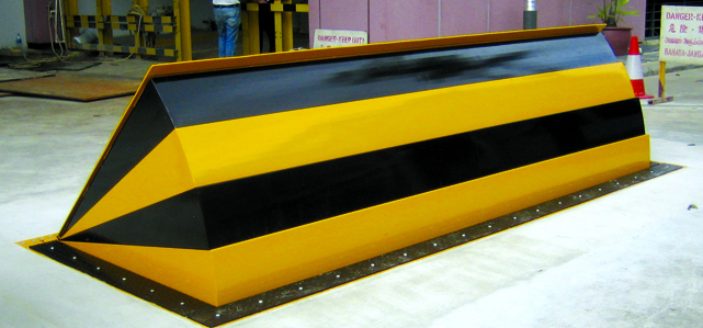
14 and the surface 12 to which the barrier 10 is secured might be made from concrete - Wedge Barriers. 2, the obstacle 10 is installed to or consists of a support or subframe (e. g., anchor 30 displayed in FIG. 2 )secured under the surface area 12. For instance, the bather 10 may be bolted to the anchor or protected to the anchor by various other mechanical fasteners. In the illustrated embodiment, the obstacle 10 includes a wedge plate 16, which includes a part that is substantially parallel with the surface area 12 when the barrier 10 remains in the retracted setting. To put it simply, lorries or individuals may pass over the barrier 10 when the barrier 10 is in the retracted placement and experience mild elevation family member to the surface area 12 while on the obstacle 10. As talked about in detail below, when the obstacle 10 remains in the deployed position, the wedge plate 16 is held and sustained in a raised placement by a training system of the obstacle 10. Furthermore, the parts 18 might be bolted or otherwise mechanically coupled to each other. In this way, repair work or substitute of one or more elements 18 might be simplified and streamlined. That is, repair work or substitute of solitary elements
18 may be done faster, conveniently, and cost properly. FIG. In certain embodiments, the support 30 might be a steel framework consisting of plates, beam of lights(e. g., I-beams ), and/or various other frameworks that are secured within the foundation 14, which may be concrete. At the surface 12, an upper side 28 of the anchor 30 may be at the very least partially subjected
, therefore enabling the accessory of the obstacle 10 to the support 30. g., threaded holes)in one or more beams or plates of the anchor 30 may be revealed to the surface 12. In this manner, screws 32 or other mechanical fasteners may be made use of to safeguard the obstacle 10 to the anchor 30. As the obstacle 10 is placed to the surface 12 of the structure 14, collection of particles and other material underneath the barrier may be lowered, and elements of the bather 10 might not be revealed to listed below dig this grade atmospheres. As indicated by referral character 52, the training device 50 includes components disposed beneath the wedge plate 16. The parts 52 underneath the wedge plate 16 may consist of an electromechanical actuator, a webcam, one or even more web cam surface areas, and so forth. In addition, the training system 50 consists of a springtime assembly 54
The spring rod 58 is paired to a cam(e. g., cam 80 received FIG. 4) of the lifting system 50. The useful source springs 60 disposed regarding the springtime pole 58 are held in compression by spring sustains 62, including a repaired springtime support 64. That is, the fixed spring support 64 is dealt with relative to the foundation 14 et cetera of the bather 10.
About Wedge Barriers
g., spring support 65 )may be taken care of to completion of the spring rod 58 to make it possible for compression of the springs 60. As the springs 60 are pressed in between the spring sustains 62, the spring assembly 54 generates a pressure acting upon the camera combined to the spring rod 58 in a direction 66. The remaining force applied to
the cam webcam deploy the wedge plate 16 may might provided by an electromechanical actuator 84 or other various other. Therefore, the spring setting up 54 and the actuator 84(e. g., electromechanical actuator)may operate together to convert the cam and lift the wedge plate check this 16.
As pointed out above, in the deployed setting, the wedge plate 16 offers to obstruct access or traveling beyond the obstacle 10. The barrier 10(e. g., the wedge plate 16 )might obstruct pedestrians or automobiles from accessing a residential property or path. If a vehicle is traveling towards the deployed wedge plate 16(e. For instance, in one situation, the safety and security legs 86 might be prolonged duringmaintenance of the barrier 10.